Switchport security associates specific MAC addresses of PCs with specific interfaces on a switch. It gives you the ability to restrict to a switch interface so that only authorised devices can use it. You can define the port action with three different modes : Protect(sends an alert),restrict(discards), shutdown(closes the port)
Implement Port security
Build a simple topology and assign IP addresses to the PCs:
In the below command list I have:
-set the switchport as an access port
-enabled port security
-defined which mac addresses are allowed through the interface (sticky dynamically learns of mac addresses currently connected to the host
Now we can define the action that the switch will take when it receives a frame from an unauthorised device. This is done using the switchport port-security violation (protect, or restrict or shutdown)
Then define the maximum number of MAC addresses that can be received on the switch using the following command switchport port-security maximum 1 (1 is the number that can be changed)
That's the configuration done for fa0/1 we just need to repeat it for Fa0/2. Interface range fa0/1-2 would have done this together to avoid doing two separate configs.
Finally if we ping between the two pcs and run the show port-security interface fa0/1 command on the switch .You can now see the maximum allowed devices, port status and the mac address that has passed through.
Each of a hosts network interfaces has a link layer MAC addressthat distinguishes it from other machines on the physical network. IP addresses are assigned to network interfaces and not machines. A mac address is made up of 48 bits or 6 bytes and is split into two parts. The first 3 bytes identify the manufacturer and the last 3 bytes are a unique serial number, so in this example the green sections are the vendor id and the black section is the interfaces unique number 32-03-C8-73-DC-A1. This is important for network engineers in spotting devices or vendors that are causing havoc on the network.
Broadcasting
Broadcasting is a send once to all method of communication. A MAC address needs to be assigned to a broadcast frame. This address is made up of all binary 1s and when converted to hexadecimal gives you FF:FF:FF:FF:FF:FF
Multicasting
Multicasting works similar to broadcasting, but instead of sending data to all it sends it to a targeted group, often called one to many transmission. Common applications that use multicasting are streaming channels like Twitch and Youtube live. To avoid collisions when an ethernet switch receives a multicast frame it floods it out of all ports except the incoming port.
MAC address tabling
A switch stores mac addresses in a table. This table is called a mac address table or a content addressable memory (CAM table). A switch stores information about other ethernet interfaces which are connected on the network. When a switch receives a frame it correlates the device sending with interface where it was received.
A MAC address table maps each and every port to a MAC address and it does this in two ways;
Static - Have higher priority than dynamic as they can be added, removed or changed by an administrator
Dynamic - Added to the table automatically by a process called MAC learning. Once a switch receives a frame it automatically updates it mac address information. There is a brief video below showing how a mac address table works in practice.
The ability to configure multiple physical links into one logical link is called an ether channel. Ether channels are a link aggregation technology and are also referred to a as port channel architecture. Once the ether channel has been configured the resulting virtual interface is called a port channel. The benefits of this are we can combine physical links to combine bandwidth, logically speaking two 100Mbps links combine into a 200Mbps link. An ether channel provides redundancy, if one port fails the other one is still active. An ether channel must be between 2 and 8 physical links
Below we will configure an ether channel in Cisco Packet tracer;
Link Aggregation Control Protocol (LACP)
LACP is an open standard which can be used by most vendors. Switch ports can form an ether channel in different LACP modes following the below criteria;
-A port in the active mode can form an Ether Channel with another port that is in the active or passive mode.
-A port in the passive mode cannot form an Ether Channel with another port that is also in the passive mode because neither port starts LACP negotiation.
A port in active mode negotiates with the other side to form the Ether channel. The interface in passive mode indicates using LACP, but responds to requests only and does not send any requests.
LACP negotiation modes for channel establishment
LACP configurations;
Here are the configurations for LACP notice the mode is set to active. On a second switch the command are the same just replace active with passive.
Manual On Ether Channel mode
When using manual on mode an ether channel will be created only when another interface is using manual on mode. They forcefully form an ether channel without negotiation.
Port aggregation protocol (PAgP)
PAgP is a Cisco proprietary ether channel technology. Switch Ports can form an Ether Channel when they are in different PAgP modes as per below criteria;
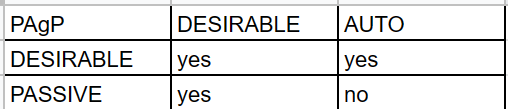
-A port in the desirable mode can form an Ether Channel with another port that is in the desirable or auto mode.
-A port in the auto mode can form an Ether Channel with another port in the desirable mode.
The port in desirable mode is one which sends requests to the other side to see if it is also using PAgP. The port in auto mode defines using PAgP but does not send requests.
PAgP negotiation modes for channel establishment
PAgp configurations
Notice here we don't need to specify the protocol as this is default on Cisco switches. On another switch the mode would be set to auto
The Spanning tree protocol (STP) is a loop free layer 2 technology. Without STP loops can occur on a network and result in a broadcast storm
Switches within the same network need to be enabled for STP before they run the spanning tree algorithm so they can accurately determine which switch should be elected the “root bridge.” This designated root bridge will be responsible for sending configuration bridge protocol data units (BPDUs) along with other information to its directly connected switches that, in turn, forward the BPDUs to their neighbouring switches. Each switch has a bridge ID priority value (BID), which is a combination of a priority value (default 32768) and the switch’s own MAC address. The switch with the lowest BID will become the root bridge.
STP Port States
There are five STP switchport states; these are:
Disabled - The result of an administrative command that will disable the port.
Blocking - When a device is connected, the port will first enter the blocking state.
Listening -The switch will listen for and send BPDUs.
Learning - The switch will receive a superior BPDU, will stop sending its own BPDUs, and will relay the superior BPDUs.
Forwarding - The port is forwarding traffic.
STP Port Roles
Root - Ports on non-root switches with the best cost path to root bridge. These ports forward data to the root bridge.
Designated - Ports on root and designated switches. All ports on the root bridge will be designated.
Blocked - All other ports to bridges or switches are in a blocked state. Access ports going to workstations or PCs are not affected.
Path cost
A switch may encounter one or more switches in its path to the root bridge. All paths are analysed and the path with the lowest cost is selected. Speed of ports are important and link speed relates to the port cost
A network switch is a layer 2 device that uses mac address to forward data frames to the layer 3 routing device. These MAC addresses are stored in a MAC address table. A MAC address table can be configured statically and those MAC addresses take priority over the more common dynamic allocations. What a mac address table does is store information about connected devices so it can efficiently switch frames between interfaces.
Store and Forward Switching vs Cut through switching
When it comes to networking, switches play a crucial role in ensuring the smooth flow of data and efficient communication between devices. Two of the most commonly used switching techniques are Store and Forward and Cut-Through. Both techniques have their pros and cons, and it's essential to understand the differences between them to make informed decisions about the most appropriate method to use in a given scenario.
Store and Forward Switching
In Store and Forward switching, the entire frame of data is received by the switch before it's forwarded to its intended destination. The switch waits until it has received the entire frame before it begins to analyze and verify the frame's header information, including the checksum, error detection, and correction. Once the switch verifies that the frame is error-free, it forwards the frame to its intended destination. This approach to switching is called "store and forward" because the switch stores the entire frame before forwarding it.
Pros:
Improved error detection: The Store and Forward technique is known for its ability to detect errors in data frames, including corrupted or damaged frames. Since the switch waits until it has received the entire frame before analyzing it, it can effectively detect errors and prevent them from being forwarded to their intended destinations.
Reduced latency: By verifying the frame's header information before forwarding it, the switch can ensure that only error-free frames are forwarded, reducing the latency of data transmission.
Cons:
Increased latency: Although the Store and Forward technique reduces latency by preventing error-prone frames from being transmitted, it also increases latency as the switch waits to receive the entire frame before forwarding it. This increase in latency can be significant in high-speed networks, where the speed of data transmission is critical.
Reduced throughput: The Store and Forward technique can also reduce network throughput as the switch waits to receive the entire frame before forwarding it. This reduction in throughput can be particularly problematic in high-speed networks where a large amount of data is being transmitted.
Cut-Through Switching
Cut-Through switching, on the other hand, is a switching technique where the switch starts forwarding the data frame as soon as it receives the destination address. The switch does not wait to receive the entire frame or verify its header information before forwarding it.
Pros:
Reduced latency: Cut-Through switching reduces latency by forwarding the data frame as soon as the switch receives the destination address, eliminating the wait time required by the Store and Forward technique.
Improved throughput: Cut-Through switching also improves network throughput by forwarding the data frame as soon as the switch receives the destination address, reducing the wait time required by the Store and Forward technique.
Cons:
Poor error detection: Cut-Through switching is not as effective as Store and Forward in detecting errors in data frames, including corrupted or damaged frames. Since the switch does not wait to receive the entire frame before forwarding it, it cannot effectively detect errors, leading to the potential for errors to be transmitted to their intended destinations.
Increased errors: Since the Cut-Through technique does not verify the header information of the frame before forwarding it, it increases the likelihood of errors in the transmitted data.
Initial Switch Configuration
When a switch is powered on it will run a POST much like any other computer. It will attempt to boot using information in the boot environment variable. If this is not set it will boot the first executable it can find. In Cisco IOS, it will initialise the configurations found in the startup-config-file ; config.text
As we have previously learned the running configuration needs to be saved to the NVRam or all changes made will be lost. To do this and save our configuration to the config.text file we follow the commands below and press enter after the ? ;
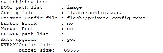
You can enter the show boot command to see what the current ios boot file is set too;
If you wanted to boot the system from a pre determined file you can use the boot system command within global configuration mode follow by flash and the file name for example; (FOC.bin is a predetermined boot file)
Cisco Switch LED Indicators
System LED (SYST): Shows whether the system is receiving power and
functioning properly.
Redundant Power Supply LED (RPS): Shows the RPS status.
Port Status LED (STAT): When green, indicates port status mode is
selected, which is the default. Port status can then be understood by the
light associated with each port.
Port Duplex LED (DUPLX): When green, indicates port duplex mode is
selected. Port duplex can then be understood by the light associated with
each port.
Port Speed LED (SPEED): When green, indicates port speed mode is
selected. Port speed can then be understood by the light associated with
each port.
Power over Ethernet LED (PoE): Present if the switch supports PoE.
Indicates the PoE status of ports on the switch.
The Mode button is used to move between the different modes – STAT,
DUPLX, SPEED, and PoE
Hosts cannot communicate with hosts on a separate VLAN unless there is a configured router in place. Inter VLAN routing is the process of forwarding one VLANs traffic to another.
The two main options for inter VLAN routing are;
1. Router on a stick for small - medium businesses
2. Layer 3 switches that use SVI's - large enterprises
A router on a stick
The router on a stick method only requires one physical ethernet interface to route traffic between multiple VLANS. This sub interface on a Cisco router is configured as a trunk connecting to a layer 2 switch using the 802.1Q protocol. the configured sub interfaces are software based and each is configured with an independent IP address and VLAN assignment. When VLAN- tagged traffic enters the router interface it is forwarded to the VLAN sub interface, then a routing decision can be made based on the destination IP address. This method does not scale beyond 50 VLANS. See below video for a simple practical scenario for configuring the router on a stick method and an image showing which interface the configurations need to take place;
Layer 3 Switching or Multilayer Switching
The router on a stick method is limited in scalability so larger organisations would be recommended to use a multi layer switch. A multi layer switch can;
-Route between VLANs using switch virtual interfaces (SVIs)
-Be configured with different methods of routing ie OSPF (This will be discussed in a later lesson)
In packet tracer the multi layer switch looks like the below. We will configure these when we discuss routing
From this post and the last lesson you should now be ready to excel in this Quiz
A VLAN is configured on a layer 2 switch. It allows a group of multiple devices to be combined into one logical network and administered like a physical network on a single logical interface. VLANs are represented by a number, common ranges are between 1-4094. A configured VLAN keeps network traffic within a broadcast domain to reduce CPU overhead and increase security.
Advantages of VLANS
- Reduces CPU overhead
- Reduces cabling costs
- Simplified management
- Traffic management
- Separate devices into groups regardless of location
Types of VLANs
A default VLAN is assigned to VLAN1. This cannot be renamed or deleted. It is the default VLAN, the default Native VLAN (a native VLAN doesn't originate from a VLA N port) and the default VLAN management VLAN (for remote SSH and telnet connections)
Data VLAN
The data VLAN is dedicated for user specific traffic such as web or email, again VLAN1 is the default interface for this type of traffic.
Native VLAN
A Native VLAN is used for trunk links and all frames are tagged with Cisco's propriety protocol 802.1Q
Management VLAN
Used for SSH and telnet connections and should not be used to carry end user traffic as a security measure
Voice VLAN
A voice VLAN is a separate VLAN for voice traffic. High bandwidth and QOS rules are applied to avoid congestion. For a voice VLAN to be effective the entire network and supporting infrastructure needs to be designed around high performance.
Inter VLAN communication
VLANS on a layer 2 switch keep traffic within a single broadcast domain. But what if you want inter vlan communication and not use a router? For this to be possible you need to have access to layer 3 switch or multi layer switch. Here you create a layer 2 vlan and then assign an IP address to the layer 3 switch much like you would on a router. This interface is call a switch virtual interface (SVI). This interface will handle the communication between vlans within sperate broadcast domains.
Viewing VLAN configurations
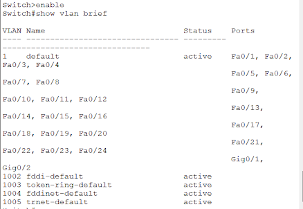
Below the show vlan brief command is used to show VLAN statuses.
VLAN configurations
VLAN creation
For starting to configure a VLAN follow the below steps. In this example the vlan id is 10 and the name assigned to it is FOC.
When you enter the show vlan brief command you can now see VLAN 10 in the list at the bottom.
Assigning a VLAN to a port
In the below example, VLAN 15 has been assigned to the FA0/18 port
Again when the show vlan brief command is entered we can see the assignment
Data and Voice VLAN creation
For creating data and voice vlans we will need to name and assign both. In the below example we have turned on qos for voice traffic for the interface.
Now when the show vlan brief is entered we get the below information and both voice and data have been assigned to FA0/10
VLAN trunks
If you want to group VLANS together into one single physical interface you use the trunking method. Here we have assigned VLAN 10,15,30 and 40 to interface FA0/1 . This could merge staff, students, marketing and hr departments together into one single physical interface.
Now when we look at the interface in more detail through the show interface fa0/1 switchport command we can see all the details. Note 802.1q is enabled which is assumed on a layer 2 switch but on a layer 3 switch 802.1q will need to be configured before the trunk mode.
Dynamic trunking
Dynamic trunking is used to auto create trunks between two switches. This can lead to problems such as increasing traffic. On some cisco switches such as the catalyst 2960 the Dynamic trunking protocol (DTP) is on by default. But can be turned off with the nonegotiate command:
Other switch port commands
Use the switchport mode command + the below to get the desired outcomes
access - permanent access mode and converts neighbouring link into an access link dynamic auto - will become a trunk interface if the neighbouring link is set to trunk or desirable mode
dynamic desirable - actively seeks to become a trunk by negotiating with other trunks with auto or desirable configured
trunk - permanent trunking mode and negotiates to convert the neighbouring link into a trunk link
For basic vlan configurations follow the below video;