Showing posts with label Cisco. Show all posts

Thursday, 11 May 2023

Cisco Express Forwarding (CEF)

Cisco express forwarding (CEF) -  contributes to the vital performance of modern networks.

CEF switching is a high-performance, Layer 3 IP switching technology developed by Cisco Systems. It serves as a forwarding mechanism for routing packets through network devices, such as routers and multilayer switches. CEF enables efficient packet forwarding by employing advanced data structures and algorithms to build and maintain a Forwarding Information Base (FIB) and an Adjacency table.

How CEF Switching Works

Unlike traditional routing methods that rely on route lookup for each packet, CEF creates a precomputed Forwarding Information Base (FIB) table during initialization. The FIB contains the necessary information to forward packets based on their destination IP addresses. This precomputation eliminates the need for per-packet route lookups, resulting in significantly improved forwarding performance.

The FIB contains next-hop information, including Layer 2 (MAC) addresses, obtained through the Adjacency table. The Adjacency table stores Layer 2 information about directly connected neighbours, such as MAC addresses or ATM addresses. CEF populates the Adjacency table dynamically, reducing the need for Address Resolution Protocol (ARP) requests for each packet.

Benefits of CEF Switching

  1. Enhanced Performance: By building and maintaining a precomputed FIB table, CEF eliminates per-packet route lookups, leading to faster packet forwarding. This acceleration improves overall network performance, reduces latency, and enhances the user experience.

  2. Load Balancing: CEF supports multiple load-balancing algorithms, such as per-destination or per-packet load balancing. These mechanisms distribute traffic across available paths, maximizing network utilization and preventing congestion on specific links.

  3. Scalability: CEF's efficient data structures and algorithms allow networks to handle high traffic volumes and scale seamlessly. Its ability to handle millions of routes with minimal impact on performance makes it suitable for large enterprise networks and service provider environments.

  4. Traffic Engineering: CEF provides granular control over traffic flow by allowing administrators to manipulate the forwarding decisions. Policy-based routing, route maps, and access control lists (ACLs) can be used to direct traffic based on specific criteria, optimizing network resources and enabling traffic engineering.

  5. Fault Tolerance: CEF enables fast convergence and minimizes network downtime in the event of link failures or network topology changes. It achieves this by maintaining accurate routing information in the FIB and using mechanisms like Cisco Express Forwarding-Independent Fast Convergence (CEF-IFC) to rapidly update forwarding tables

Tuesday, 18 April 2023

Basic Wireless Home Security

Wireless security is generally controlled through a nice GUI these days. It is relatively straight forward to administer as most users are home users. Home networks are configured for the masses and are not necessarily secure especially if used in business. Below are some key features exampled using Cisco Packet Tracer's WRT300N Router

SSID Cloaking

By default home routers display their SSID (ie BT7891XN). The SSID is the name of the network. This is a security risk and should be hidden to avoid an open door. In the below image the SSID broadcast is set to disabled which prevents the SSID being displayed to available devices and it will need to be entered manually in order to connect.


Access Restrictions

To edit access restrictions and only allow certain IP addresses and MAC addresses to connect, under access restrictions click edit list.


This will allow you to enter the IP ranges or specific IP addresses allowed to connect to your wireless networks


Further down on the access restriction tab you can block websites, applications or keywords (packet tracer is a bit restrictive in this department


Configuring keyword blocking is important these days if you have young children, but also certain websites that you may not want to see your colleagues or family members access are also very important measures.

Dynamic ARP Inspection (DAI)

Address Resolution Protocol (ARP) is a layer 2 protocol. It simply maps an IP address to a mac address.

When a PC communicates with another the arp table is updated with the command arp -a (shown below)


Why DAI?

Within a man-in the middle attack - typically arp spoofing. A rogue pc/laptop sends a spoof arp message which associates the attackers mac address with that of the router or other device on the network so that it can intercept and alter traffic. DAI on the switch compares the incoming ARP packet and entries should be matched in the DHCP snooping binding table, and any ARP access control lists. If the ARP doesn't match the switch will disregard the ARP request. 

Configurations

To configure DAI and validate the source mac address against the sender's mac address within the ARP body we use this can be seen in the show ip arp inspection image that src mac address is validated; 


To enable DAI on a VLAN 1 we use :


If we now run the show ip inspection vlan 1 command we see source mac validation is enabled:


To enable the trust interface state on fast ethernet 0/1:


And verify the configuration:


Access control 

Cisco packet tracer doesn't currently support the creation of ARP access lists but essentially it is permitting the access of an IP address and MAC address through an interface just like the below


Monday, 17 April 2023

Cisco Router password security basics

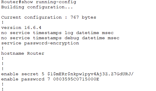
In the below screenshot we have created two simple passwords for two different modes. The highlighted yellow is a password for user mode whereas the password in green is for privileged mode. Following on from creating the passwords good practice is to encrypt the passwords


Now when we run the show running-config command we don't see the passwords in plain text but in an encrypted format.


Here are a couple of video walkthroughs configuring what was previously mentioned. 

Video1

Video2

Some basic network troubleshooting commands

Below are some every day, useful commands to use when troubleshooting your own device and network issues

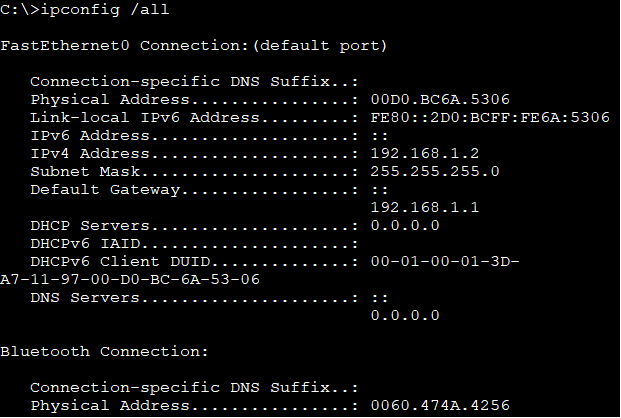
ipconfig /all

This command shows the current TCP/IP configurations for all adapters. This can be both logical and physical addresses. Below is a simple screenshot with the results. Notice the default gateway is shown, this is the router address on the same network as the device. Without the default gateway being configured we will not be able to communicate remotely or with other networks. 


show ip interface brief

This is a router command it shows all IPv4 interface configurations and their current status


ping

Ping verifies IP connectivity to another networked device by sending Internet Control Message Protocol (ICMP) echo Request messages. When a successful ping happens you get the below pieces of information. In the example 127.0.0.1 is a loopback address to check if the local PC's TCP/IP address is configured correctly. If an IP address is not available you will get a timed out message.


tracert

Trace route will diagnose the path taken to a destination. Again ICMP is used, and echo requests are feedback when a different network is identified. This is used to pinpoint where network failures occur


These are just some small examples of commands that can be used at a fundamental level. Microsoft have published a detailed list of commands here


Tuesday, 21 March 2023

Port security - Cisco switches

Switchport security associates specific MAC addresses of PCs with specific interfaces on a switch. It gives you the ability to restrict to a switch interface so that only authorised devices can use it. You can define the port action with three different modes : Protect(sends an alert), restrict(discards), shutdown(closes the port)


Implement Port security 

Build a simple topology and assign IP addresses to the PCs:

In the below command list I have:
-set the switchport as an access port 
-enabled port security
-defined which mac addresses are allowed through the interface (sticky dynamically learns of mac addresses currently connected to the host


Now we can define the action that the switch will take when it receives a frame from an unauthorised device. This is done using the switchport port-security violation (protect, or restrict or shutdown) 
Then define the maximum number of MAC addresses that can be received on the switch using the following command switchport port-security maximum 1 (1 is the number that can be changed)


That's the configuration done for fa0/1 we just need to repeat it for Fa0/2. Interface range fa0/1-2 would have done this together to avoid doing two separate configs.

Finally if we ping between the two pcs and run the show port-security interface fa0/1 command on the switch .You can now see the maximum allowed devices, port status and the mac address that has passed through.


AAA - Authentication, Authorisation, Accounting

802.1X authentication

802.1X authentication involves ensuring something is what its saying it is.

Features

Supplicant - (client-end user) - Devices that are trying to connect to an 802.1X need to have software installed on them and this is known as a supplicant. The supplicant initiates the connection by activating EAP (Extensible Authentication Protocol) between the device and switch

Authenticator - A device on a network that connects a client to a network. It blocks and allows traffic. A switch is an example of an authenticator.

Authentication Server - deals with requests for access to the network. The server tells the authenticator to allow or deny the traffic. Authentication servers usually run on the RADIUS protocol.


AAA

AAA is a requirement of network security. It is a process from start to finish of network access and monitoring

Authentication: uses challenge and response methodology for granting access. This identifies users by username and password

Authorisation: After initial authentication, authorisation uses the RADIUS protocol to allow access to resources based on permission levels

Accounting: After access users can be be monitoring for billing, reporting and auditing. You can observe what users do after they have been authenticated and authorised for example when they log in and when they log out.


The next steps are to look at a practical scenario using the AAA methodology.

Topology addressing:

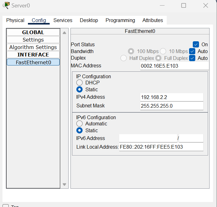
Server: 192.168.2.2

G/0/0/1: 192.168.2.1

G/0/0/0: 192.168.1.1

PC0: 192.168.1.2 (Default Gateway 192.168.1.1)


Configure IP addressing on the router:


Assign a valid IP address to your Radius Server:


Turn on AAA on the services tab, add the the router details for the network the server is on ands specify a passkey - here I have used "hello"


Configuring AAA on the router, specify the server address and the passkey you used. (note the passkey I used is not very secure so something with multiple characters, number etc may be better)


Enable remote login:


Assign an IP address for your PC:


Test the telnet connection:


Note here: To use the more secure SSH connection you would need to add the ssh configurations into the router and it is also good practice to enable passwords on your router which was discussed in previous posts. 


Wednesday, 8 March 2023

Hot Standby Routing Protocol ( HSRP)

HSRP is a Cisco proprietary protocol that provides redundancy within a subnet. A virtual router is created which acts as the default gateway and a priority number is assigned to the physical routers to determine which is active and which is a standby router. 

Some key concepts with HSRP;

Priority

By default the priority number is 100. The highest priority number configured is assigned the active router if that fails then the next highest takes over which is the standby router. For example a priority number of 150 would be the active and 100 would be the standby router. 

Preempt

Is a state which activates the active router automatically

Hello messages

Are exchanged periodically to activate the standby router if it detects a failure on the network.


Virtual IP address 

A logical IP address that each host uses as the default gateway within a local subnet. 


Practical activity

In the below video, there is a full run through of HSRP in action. There is also the side effect concept of OSPF which is a routing protocol that dynamically routes traffic based on administrative distance. 


MAC Address Basics

Each of a hosts network interfaces has a link layer MAC address that distinguishes it from other machines on the physical network. IP addresses are assigned to network interfaces and not machines. A mac address is made up of 48 bits or 6 bytes and is split into two parts. The first 3 bytes identify the manufacturer and the last 3 bytes are a unique serial number, so in this example the green sections are the vendor id and the black section is the interfaces unique number 32-03-C8-73-DC-A1. This is important for network engineers in spotting devices or vendors that are causing havoc on the network. 

Broadcasting

Broadcasting is a send once to all method of communication. A MAC address needs to be assigned to a broadcast frame. This address is made up of all binary 1s and when converted to hexadecimal gives you FF:FF:FF:FF:FF:FF

Multicasting

Multicasting works similar to broadcasting, but instead of sending data to all it sends it to a targeted group, often called one to many transmission. Common applications that use multicasting are streaming channels like Twitch and Youtube live. To avoid collisions when an ethernet switch receives a multicast frame it floods it out of all ports except the incoming port.

MAC address tabling

A switch stores mac addresses in a table. This table is called a mac address table or a content addressable memory (CAM table).  A switch stores information about other ethernet interfaces which are connected on the network. When a switch receives a frame it correlates the device sending with interface where it was received. 

A MAC address table maps each and every port to a MAC address and it does this in two ways;

Static - Have higher priority than dynamic as they can be added, removed or changed by an administrator

Dynamic - Added to the table automatically by a process called MAC learning. Once a switch receives a frame it automatically updates it mac address information. There is a brief video below showing how a mac address table works in practice. 


Wednesday, 1 March 2023

DHCPv6 configurations with Stateful and Stateless (SLAAC)

DHCPv6 as a concept is very similar to version 4. There are some key differences that we need to know. DHCPv6 supports two very different methods; Stateful and stateless configurations.

Stateful

Stateful configuration works pretty much the same as DHCPv4. The DHCP server assigns the IP address to the client. When DHCPv6 addresses are being sent from a server to a client it uses UDP destination port 546


Stateless (SLAAC)

Stateless on the other hand uses autoconfiguration. Routers running IPv6 can give the prefix of the network and a gateway address to clients looking for an IPv6 address. IPv6 uses the Neighbour Discovery, and one of the things this protocol offers is Route Solicitation and Router Advertisement messages that help an IPv6 device configure an IPv6 address automatically. The router is configured to send out Router advertisements periodically.
Router Advertisement messages inform hosts what to do - There are three flags in the RA messages that play important role in defining how dynamic addressing works on this segment:
  • A-flag - if it is set to 1, this informs hosts that they can auto-generate GUA address using SLAAC. If it is set to 0 means that auto-configuration is not allowed for this segment.
  • O-flag - if it is set to 1, this informs hosts that they can obtain a DNS server list and a domain name from a Stateless DHCPv6 server, but not addressing information. Typically it works in conjunction with SLAAC for auto-addressing and both the A-flag and the O-flag are set to 1.
  • M-flag - if it is set to 1, this informs hosts that they can obtain a global address as well as DNS and a domain name from a Stateful DHCPv6 server. Typically this means that auto-addressing using SLAAC is not allowed on this segment and both the  A-flag and the O-flag are set to 0.

A host sends out a router solicitation message which is a multicast address for all routers which is FF02::2. The Router Advertisement contains the Prefix Information (prefix (network address), prefix length (subnet mask), and default gateway). The host uses this information to generate an IPv6 address (global unicast address or GUA) for itself. The host then employs Duplicate Address Detection to ensure that its address is unique.

2. On the router use the below configurations from the screenshot;

Configurations

Lets look at how we configure SLAAC;

1. Build a simple network similar to the below

-ipv6 unicast-routing (enables the router for IPv6 routing)

-interface gigabitethernet0/0/0 (this is the particular interface being used for the connection to the switch)

-ipv6 address (is an IPv6 address which in this instance in the address of the router)


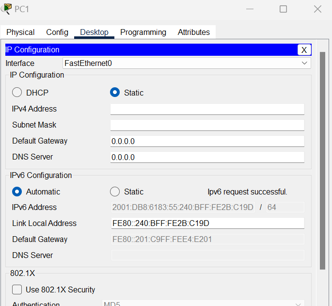
3.On each PC change the IPv6 configuration to automatic.


You will now find that the PC generates a Global Unicast Ipv6 Address on its own, with the Default Gateway address and the Link-Local Address from the Router Advertisement.

Ipv6, SLAAC and EUI

The EUI (extended Unique Identifier) uses the MAC address to generate a unique 64 bit interface ID. An Ipv6 address is 128bits and a MAC address is 48 bits so an operation needs to be performed. 

  • The hexadecimal value of FFF0(16-bits) is added in the middle of the 48-bit mac address.
  • The 7th bit from the start is toggled from 0 to 1.

For example: 

For the MAC address FC:99:47:75:CE:E0  the steps are performed as shown in the below:


Cisco routers are configured to use the EUI-64 ID generation by default.


Here is a video showing the configuration in action;


DHCP v4

Dynamic Host Configuration Protocol (DHCP)

DHCP dynamically allocates an IP address from either a pre configured router or a server. DHCP is managed centrally and saves administration time but if configured incorrectly can lead to devices not being able to connect to the network. When a device is given an IP address the DHCP server also gives out a subnet mask, DNS information and default gateway. DHCP communicates on UDP source port 68 and destination port 67. Below is an image of the process when DHCP is enabled on a client. Discover -> Offer -> Request -> Acknowledge


-During a DHCP discover message a client uses layer 2 and layer 3 broadcast message to find a DHCP server.
-During the offer message a server sends a unicast message to the requesting client.
-During the request message the client returns with a broadcast message to the server requesting an IP address
-Finally the acknowledgement message is a unicast message from the server to client with the IP address.

The key terms within DHCP configurations are; 
  • DHCP pool
  • Network address 
  • Default Gateway
  • Subnet Mask 
Here is a simple video of IPv4 DHCP configurations in packet tracer showing the benefits through automation;


Tuesday, 28 February 2023

Ether channels - Cisco Switching PAgP, LACP

Ether channels

The ability to configure multiple physical links into one logical link is called an ether channel. Ether channels are a link aggregation technology and are also referred to a as port channel architecture. Once the ether channel has been configured the resulting virtual interface is called a port channel. The benefits of this are we can combine physical links to combine bandwidth, logically speaking two 100Mbps links combine into a 200Mbps link. An ether channel provides redundancy, if one port fails the other one is still active. An ether channel must be between 2 and 8 physical links

Below we will configure an ether channel in Cisco Packet tracer;


Link Aggregation Control Protocol (LACP)

LACP is an open standard which can be used by most vendors. Switch ports can form an ether channel in different LACP modes following the below criteria; 

-A port in the active mode can form an Ether Channel with another port that is in the active or passive mode.
-A port in the passive mode cannot form an Ether Channel with another port that is also in the passive mode because neither port starts LACP negotiation.

A port in active mode negotiates with the other side to form the Ether channel. The interface in passive mode indicates using LACP, but responds to requests only and does not send any requests.

LACP negotiation modes for channel establishment


LACP configurations;


Here are the configurations for LACP notice the mode is set to active. On a second switch the command are the same just replace active with passive.


Manual On Ether Channel mode

When using manual on mode an ether channel will be created only when another interface is using manual on mode. They forcefully form an ether channel without negotiation. 


Port aggregation protocol (PAgP)

PAgP is a Cisco proprietary ether channel technology. Switch Ports can form an Ether Channel when they are in different PAgP modes as per below criteria;

-A port in the desirable mode can form an Ether Channel with another port that is in the desirable or auto mode.
-A port in the auto mode can form an Ether Channel with another port in the desirable mode.

The port in desirable mode is one which sends requests to the other side to see if it is also using PAgP. The port in auto mode defines using PAgP but does not send requests. 

PAgP negotiation modes for channel establishment


PAgp configurations

Notice here we don't need to specify the protocol as this is default on Cisco switches. On another switch the mode would be set to auto


Spanning Tree Protocol - STP

Spanning Tree Protocol

The Spanning tree protocol (STP) is a loop free layer 2 technology. Without STP loops can occur on a network and result in a broadcast storm

Switches within the same network need to be enabled for STP before they run the spanning tree algorithm so they can accurately determine which switch should be elected the “root bridge.” This designated root bridge will be responsible for sending configuration bridge protocol data units (BPDUs) along with other information to its directly connected switches that, in turn, forward the BPDUs to their neighbouring switches. Each switch has a bridge ID priority value (BID), which is a combination of a priority value (default 32768) and the switch’s own MAC address. The switch with the lowest BID will become the root bridge.

STP Port States

There are five STP switchport states; these are:

  • Disabled - The result of an administrative command that will disable the port.
  • Blocking - When a device is connected, the port will first enter the blocking state.
  • Listening -The switch will listen for and send BPDUs.
  • Learning - The switch will receive a superior BPDU, will stop sending its own BPDUs, and will relay the superior BPDUs.
  • Forwarding - The port is forwarding traffic.

STP Port Roles

  • Root - Ports on non-root switches with the best cost path to root bridge. These ports forward data to the root bridge.
  • Designated - Ports on root and designated switches. All ports on the root bridge will be designated.
  • Blocked - All other ports to bridges or switches are in a blocked state. Access ports going to workstations or PCs are not affected.


Path cost

A switch may encounter one or more switches in its path to the root bridge. All paths are analysed and the path with the lowest cost is selected. Speed of ports are important and link speed relates to the port cost


Example Video with STP ; 


Thursday, 9 February 2023

Switch basics

A network switch is a layer 2 device that uses mac address to forward data frames to the layer 3 routing device. These MAC addresses are stored in a MAC address table. A MAC address table can be configured statically and those MAC addresses take priority over the more common dynamic allocations. What a mac address table does is store information about connected devices so it can efficiently switch frames between interfaces. 


Store and Forward Switching vs Cut through switching

When it comes to networking, switches play a crucial role in ensuring the smooth flow of data and efficient communication between devices. Two of the most commonly used switching techniques are Store and Forward and Cut-Through. Both techniques have their pros and cons, and it's essential to understand the differences between them to make informed decisions about the most appropriate method to use in a given scenario.

Store and Forward Switching

In Store and Forward switching, the entire frame of data is received by the switch before it's forwarded to its intended destination. The switch waits until it has received the entire frame before it begins to analyze and verify the frame's header information, including the checksum, error detection, and correction. Once the switch verifies that the frame is error-free, it forwards the frame to its intended destination. This approach to switching is called "store and forward" because the switch stores the entire frame before forwarding it.

Pros:

  • Improved error detection: The Store and Forward technique is known for its ability to detect errors in data frames, including corrupted or damaged frames. Since the switch waits until it has received the entire frame before analyzing it, it can effectively detect errors and prevent them from being forwarded to their intended destinations.

  • Reduced latency: By verifying the frame's header information before forwarding it, the switch can ensure that only error-free frames are forwarded, reducing the latency of data transmission.

Cons:

  • Increased latency: Although the Store and Forward technique reduces latency by preventing error-prone frames from being transmitted, it also increases latency as the switch waits to receive the entire frame before forwarding it. This increase in latency can be significant in high-speed networks, where the speed of data transmission is critical.

  • Reduced throughput: The Store and Forward technique can also reduce network throughput as the switch waits to receive the entire frame before forwarding it. This reduction in throughput can be particularly problematic in high-speed networks where a large amount of data is being transmitted.

Cut-Through Switching

Cut-Through switching, on the other hand, is a switching technique where the switch starts forwarding the data frame as soon as it receives the destination address. The switch does not wait to receive the entire frame or verify its header information before forwarding it.

Pros:

  • Reduced latency: Cut-Through switching reduces latency by forwarding the data frame as soon as the switch receives the destination address, eliminating the wait time required by the Store and Forward technique.

  • Improved throughput: Cut-Through switching also improves network throughput by forwarding the data frame as soon as the switch receives the destination address, reducing the wait time required by the Store and Forward technique.

Cons:

  • Poor error detection: Cut-Through switching is not as effective as Store and Forward in detecting errors in data frames, including corrupted or damaged frames. Since the switch does not wait to receive the entire frame before forwarding it, it cannot effectively detect errors, leading to the potential for errors to be transmitted to their intended destinations.

  • Increased errors: Since the Cut-Through technique does not verify the header information of the frame before forwarding it, it increases the likelihood of errors in the transmitted data.

Initial Switch Configuration


When a switch is powered on it will run a POST much like any other computer. It will attempt to boot using information in the boot environment variable. If this is not set it will boot the first executable it can find. In Cisco IOS, it will initialise the configurations found in the startup-config-file ; config.text

As we have previously learned the running configuration needs to be saved to the NVRam or all changes made will be lost. To do this and save our configuration to the config.text file we follow the commands below and press enter after the ? ; 


You can enter the show boot command to see what the current ios boot file is set too;


If you wanted to boot the system from a pre determined file you can use the boot system command within global configuration mode follow by flash and the file name for example;  (FOC.bin is a predetermined boot file)


Cisco Switch LED Indicators

System LED (SYST): Shows whether the system is receiving power and functioning properly. 
Redundant Power Supply LED (RPS): Shows the RPS status. Port Status LED (STAT): When green, indicates port status mode is selected, which is the default. Port status can then be understood by the light associated with each port. 
Port Duplex LED (DUPLX): When green, indicates port duplex mode is selected. Port duplex can then be understood by the light associated with each port. 
Port Speed LED (SPEED): When green, indicates port speed mode is selected. Port speed can then be understood by the light associated with each port. 
Power over Ethernet LED (PoE): Present if the switch supports PoE. Indicates the PoE status of ports on the switch. 
The Mode button is used to move between the different modes – STAT, DUPLX, SPEED, and PoE 

Fast switching vs Process switching

Process Switching: Process switching is the traditional method of packet forwarding used in early routers. When a packet arrives at a router...