Showing posts with label routing. Show all posts

Wednesday, 3 May 2023

More on routing....

Routing refers to the best path for network traffic to travel. Communication at layer 2 uses mac address tables whereas layer 3 communication uses routing tables. I will discuss the different types of routing below;  

Static Routing

Static routing is the most basic type of routing and involves configuring the routing tables manually. In static routing, the network administrator defines the routes that packets can take through the network. This routing type is ideal for small networks with a limited number of devices as it is easy to configure, but it is not scalable for large networks. They are also ideal for internal networks designed for no external communications. These networks are commonly called stub networks. In a fully specified static route both the exit interface and the next hop IP address are specified. We will work through this below;

Configuring static routes 

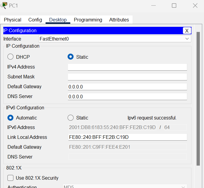
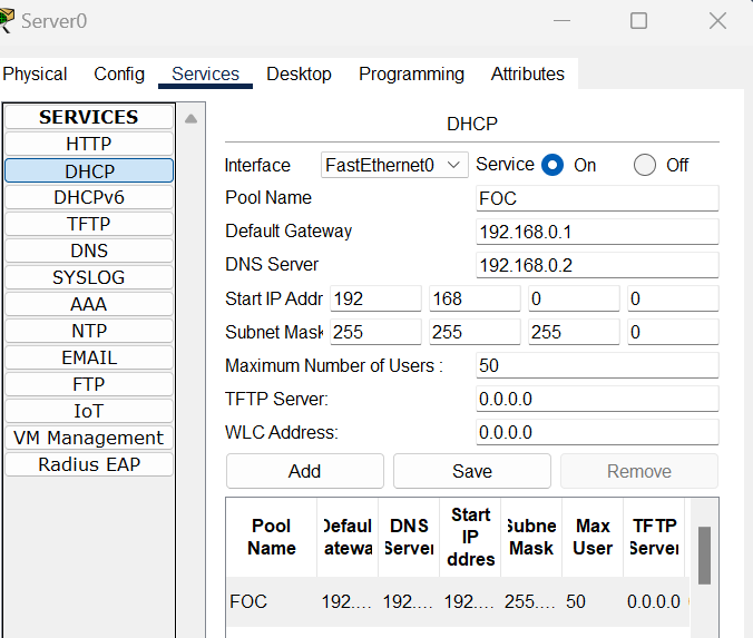
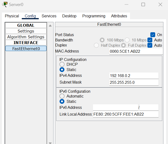
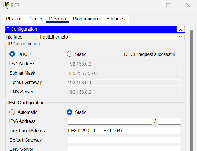
Build a simple topology and configure relevant interfaces and pcs with IP addresses.


On router 0 we want to configure the route back to the network. We only need to configure routes which are not directly connected. The command is shown below, the first IP is the network address on the furthest right followed by the subnet mask, then you need to specify the exit interfaces IP address as shown below;


On router 1 the same logic applies;


When we look up the routing table on Router 0 using the show ip route command we can see which networks are local(L), which are connected(C) and which are static (S) notice here the (L) - Local host routes have a /32 prefix with an administrative distance of 0, (more on administrative distance below). Cisco automatically installs a host route when the interface is configured on the router. It adds efficiencies for packets coming into the router rather than forwarding. 


Summary Static routing

A summary route is one route that represents multiple networks. Summary routes can also be called route aggregation. Summary routes are used to;

  • Save memory 
  • Save bandwidth
  • Stability within the routing table
  • Saves CPU cycles

To calculate a summary rout we convert each of the IP addresses to binary, so here we have 4 IP addresses that we want to summarise. 
172.16.0.0 /16
172.17.0.0 /16
172.18.0.0 /16
172.19.0.0 /16

Below are the IP addresses written in IP form then the next step is to match all all the matching bits that aren't all zeros (highlighted in green)

10101100.00010000.00000000.00000000 (172.16.0.0)
10101100.00010001.00000000.00000000 (172.17.0.0)
10101100.00010010.00000000.00000000 (172.18.0.0)
10101100.00010011.00000000.00000000 (172.19.0.0)

We can now add them bits to give us our CIDR notation of /14 (14 bits) 
To get out network address use the same 14 bits and add zeros until your get to 32 bits the form the complete answer below. 

172.16.0.0/14 - Subnet mask 
255.252.0.0

Practical application of summary routes


From the above topology configure the relevant IP addresses on devices.

192.168.1.0   11000000.10101000.00000001.00000000
192.168.2.0   11000000.10101000.00000010.00000000
192.168.3.0   11000000.10101000.00000011.00000000


192.168.0.0/22  subnet mask 255.255.252.0


Router1 configuration (notice here I have used the exit interface physical value


Same process on Router0 as the interface is the same


Default routes 

Default routing is a type of routing that is used when a router cannot find a specific route to a destination network. Instead, the router forwards the packet to a default gateway or next-hop router. This type of routing is useful for conserving network resources and reducing the size of routing tables.

Configuring default routes and the gateway of last resort

Using a similar topology as the prior example, configure the relevant IP addresses for devices, matching their networks.


Once IP addresses have been assigned, starting with router0 use the below command, the 0.0.0.0 and 0.0.0.0 are default network and subnet masks and the IP address is the gateway of last resort which is the next hop address.


Similarly on Router1


Now when will look up the routing table we can see the gateway of last resort is linked to the default network route.


Gateway of last resort

A gateway of last resort is used to forward IP packets where the destination is not listed in a routing table. in simple terms if the forwarding route is not known or specified it will be forwarded to the Gateway of last Resort. It is useful if a path becomes unavailable or you want to save space in a routing table and cut down on admin time.


Dynamic routing

Dynamic routing is a type of routing that automatically updates routing tables in response to changes in the network topology. In dynamic routing, routers use routing protocols such as OSPF (Open Shortest Path First), RIP (Routing Information Protocol), and BGP (Border Gateway Protocol) to exchange routing information with other routers in the network. This type of routing is suitable for large networks that are subject to frequent changes in topology.

Link to RIP article here

Administrative distance

Floating static routes are often used with dynamic routing. For example with two exit points out of a router one exit point may be configured for dynamic routing and the other for static routing. This is where administrative distance comes in. The router chooses the highest number for its chosen path. Administrative distance goes off the number of hops and each protocol has a specific default administrative distance for each router. Some of these are shown below;

Connected 0 
Static 1
Rip 120
OSPF 110

If a router is using the dynamic protocol of RIP for exit 1 and a static route for exit 2 the administrative distance needs to be set higher than the defaults for RIP to make that the primary route. (nb When the administrative distance is set to the same number the router sends packets equally across both paths)

For example; 


RIPv1 vs RIPv2 (Routing Information Protocol)

RIP (Routing Information Protocol) is an interior gateway protocol that exchanges information between routers on networks. Version 2 has seen improvements by allowing classless routing, multicasting and support for variable length subnetting. 


Features of RIPv2:

  1. Classless Routing: RIPv2 supports classless routing, which means it can handle networks with different subnet masks. This is an improvement over RIPv1, which only supported classful routing.

  2. Multicasting: RIPv2 uses multicast to send and receive routing updates, which reduces network traffic and improves scalability.

  3. VLSM Support: RIPv2 supports variable-length subnet masks (VLSM), which allows for more efficient use of IP address space.

  4. Authentication: RIPv2 supports authentication, which helps to prevent unauthorized updates to the routing table.

  5. Hop Count Limit: RIPv2 has a hop count limit of 15, which means that routes with a higher hop count are considered unreachable.

  6. By default routing updates are sent to other routers every 30 seconds

How RIPv2 Works:

RIPv2 uses distance vector routing to exchange routing information between routers. Each router sends its routing table to its neighbours, and each router updates its own routing table based on the information received from its neighbours.

RIPv2 uses a metric called hop count to determine the best path to a destination network. The hop count is the number of routers that a packet must pass through to reach the destination network. RIPv2 assigns a default hop count of 1 to directly connected networks, and adds 1 to the hop count for each router that the packet passes through.

Configuring RIP

Build a topology similar to the below and configure the the relevant interfaces on each router. 


Once the topology has been configured the simple commands for enabling and configuring RIP are below. I have added the network addresses with the highlighted green arrows for the addresses to be added to the RIP database


Show rip database...


Additional commands with RIP


default-information originate is used to generate a default route in the RIP database


passive-interface to stop routing updates on an interface


More additions can be found using the ? command


Monday, 17 April 2023

Basic routing types


Static, Default, and Dynamic Routing: What's the Difference?

When it comes to routing, there are three main types: static, default, and dynamic. Each type has its own advantages and disadvantages, so it's important to choose the right one for your network.

Static routing is the simplest type of routing. In static routing, the network administrator manually configures the routes in the routing table. This means that the administrator must manually add or remove routes as needed. Static routing is easy to configure and maintain, but it can be time-consuming to manage large networks.

Default routing is a type of static routing that uses a single route to all destinations that are not explicitly defined in the routing table. This is a good option for small networks with a single exit point to the internet. Default routing is easy to configure and maintain, but it can be less efficient than dynamic routing.

Dynamic routing is a more complex type of routing that uses algorithms to automatically update the routing table. This means that the network administrator does not need to manually add or remove routes. Dynamic routing is more efficient than static routing, but it can be more complex to configure and maintain.

Which type of routing is right for you?

The best type of routing for you will depend on the size and complexity of your network. If you have a small network with a single exit point to the internet, then default routing may be a good option. If you have a large network with multiple exit points to the internet, then dynamic routing may be a better option.

Wednesday, 8 March 2023

Hot Standby Routing Protocol ( HSRP)

HSRP is a Cisco proprietary protocol that provides redundancy within a subnet. A virtual router is created which acts as the default gateway and a priority number is assigned to the physical routers to determine which is active and which is a standby router. 

Some key concepts with HSRP;

Priority

By default the priority number is 100. The highest priority number configured is assigned the active router if that fails then the next highest takes over which is the standby router. For example a priority number of 150 would be the active and 100 would be the standby router. 

Preempt

Is a state which activates the active router automatically

Hello messages

Are exchanged periodically to activate the standby router if it detects a failure on the network.


Virtual IP address 

A logical IP address that each host uses as the default gateway within a local subnet. 


Practical activity

In the below video, there is a full run through of HSRP in action. There is also the side effect concept of OSPF which is a routing protocol that dynamically routes traffic based on administrative distance. 


Wednesday, 1 March 2023

DHCPv6 configurations with Stateful and Stateless (SLAAC)

DHCPv6 as a concept is very similar to version 4. There are some key differences that we need to know. DHCPv6 supports two very different methods; Stateful and stateless configurations.

Stateful

Stateful configuration works pretty much the same as DHCPv4. The DHCP server assigns the IP address to the client. When DHCPv6 addresses are being sent from a server to a client it uses UDP destination port 546


Stateless (SLAAC)

Stateless on the other hand uses autoconfiguration. Routers running IPv6 can give the prefix of the network and a gateway address to clients looking for an IPv6 address. IPv6 uses the Neighbour Discovery, and one of the things this protocol offers is Route Solicitation and Router Advertisement messages that help an IPv6 device configure an IPv6 address automatically. The router is configured to send out Router advertisements periodically.
Router Advertisement messages inform hosts what to do - There are three flags in the RA messages that play important role in defining how dynamic addressing works on this segment:
  • A-flag - if it is set to 1, this informs hosts that they can auto-generate GUA address using SLAAC. If it is set to 0 means that auto-configuration is not allowed for this segment.
  • O-flag - if it is set to 1, this informs hosts that they can obtain a DNS server list and a domain name from a Stateless DHCPv6 server, but not addressing information. Typically it works in conjunction with SLAAC for auto-addressing and both the A-flag and the O-flag are set to 1.
  • M-flag - if it is set to 1, this informs hosts that they can obtain a global address as well as DNS and a domain name from a Stateful DHCPv6 server. Typically this means that auto-addressing using SLAAC is not allowed on this segment and both the  A-flag and the O-flag are set to 0.

A host sends out a router solicitation message which is a multicast address for all routers which is FF02::2. The Router Advertisement contains the Prefix Information (prefix (network address), prefix length (subnet mask), and default gateway). The host uses this information to generate an IPv6 address (global unicast address or GUA) for itself. The host then employs Duplicate Address Detection to ensure that its address is unique.

2. On the router use the below configurations from the screenshot;

Configurations

Lets look at how we configure SLAAC;

1. Build a simple network similar to the below

-ipv6 unicast-routing (enables the router for IPv6 routing)

-interface gigabitethernet0/0/0 (this is the particular interface being used for the connection to the switch)

-ipv6 address (is an IPv6 address which in this instance in the address of the router)


3.On each PC change the IPv6 configuration to automatic.


You will now find that the PC generates a Global Unicast Ipv6 Address on its own, with the Default Gateway address and the Link-Local Address from the Router Advertisement.

Ipv6, SLAAC and EUI

The EUI (extended Unique Identifier) uses the MAC address to generate a unique 64 bit interface ID. An Ipv6 address is 128bits and a MAC address is 48 bits so an operation needs to be performed. 

  • The hexadecimal value of FFF0(16-bits) is added in the middle of the 48-bit mac address.
  • The 7th bit from the start is toggled from 0 to 1.

For example: 

For the MAC address FC:99:47:75:CE:E0  the steps are performed as shown in the below:


Cisco routers are configured to use the EUI-64 ID generation by default.


Here is a video showing the configuration in action;


DHCP v4

Dynamic Host Configuration Protocol (DHCP)

DHCP dynamically allocates an IP address from either a pre configured router or a server. DHCP is managed centrally and saves administration time but if configured incorrectly can lead to devices not being able to connect to the network. When a device is given an IP address the DHCP server also gives out a subnet mask, DNS information and default gateway. DHCP communicates on UDP source port 68 and destination port 67. Below is an image of the process when DHCP is enabled on a client. Discover -> Offer -> Request -> Acknowledge


-During a DHCP discover message a client uses layer 2 and layer 3 broadcast message to find a DHCP server.
-During the offer message a server sends a unicast message to the requesting client.
-During the request message the client returns with a broadcast message to the server requesting an IP address
-Finally the acknowledgement message is a unicast message from the server to client with the IP address.

The key terms within DHCP configurations are; 
  • DHCP pool
  • Network address 
  • Default Gateway
  • Subnet Mask 
Here is a simple video of IPv4 DHCP configurations in packet tracer showing the benefits through automation;


Thursday, 9 February 2023

Inter VLAN routing

Hosts cannot communicate with hosts on a separate VLAN unless there is a configured router in place. Inter VLAN routing is the process of forwarding one VLANs traffic to another.

The two main options for inter VLAN routing are;

1. Router on a stick for small - medium businesses

2. Layer 3 switches that use SVI's - large enterprises

A router on a stick

The router on a stick method only requires one physical ethernet interface to route traffic between multiple VLANS. This sub interface on a Cisco router is configured as a trunk connecting to a layer 2 switch using the 802.1Q protocol. the configured sub interfaces are software based and each is configured with an independent IP address and VLAN assignment. When VLAN- tagged traffic enters the router interface it is forwarded to the VLAN sub interface, then a routing decision can be made based on the destination IP address. This method does not scale beyond 50 VLANS. See below video for a simple practical scenario for configuring the router on a stick method and an image showing which interface the configurations need to take place;


Layer 3 Switching or Multilayer Switching

The router on a stick method is limited in scalability so larger organisations would be recommended to use a multi layer switch. A multi layer switch can;
-Route between VLANs using switch virtual interfaces (SVIs)
-Be configured with different methods of routing ie OSPF (This will be discussed in a later lesson)

In packet tracer the multi layer switch looks like the below. We will configure these when we discuss routing


From this post and the last lesson you should now be ready to excel in this Quiz

Monday, 30 January 2023

Static vs dynamic IP addresses - configurations

Knowledge 

A static IP address is a permanent, fixed address assigned to a device on a network, rather than being assigned dynamically by a DHCP server. This allows for easier network administration and can help with specific applications such as remote access or website hosting.


DHCP stands for Dynamic Host Configuration Protocol. It is a network protocol used to dynamically assign IP addresses to devices on a network. DHCP allows for automatic and centralized management of IP addresses, reducing the manual effort required to configure devices on a network. It helps ensure that each device has a unique IP address and eliminates the risk of IP address conflicts. 

Skill


DHCP from a router

Set a simulation environment similar to the below


Assign  the IP address

On the router enter the commands below. Here ip address 192.168.0.1 with default subnet mask 255.255.255.0 has been assigned to interface gigabitethernet 0/0/0


Configure DCHP pool

Here the DHCP pool has been named "FOC" the network address has been assigned to the pool "192.168.0.0" and the default router: "192.168.0.1" . The default router address will give the default gateway address to the devices requesting a DHCP ip address. The final commands exclude an IP range. This range is outside the DHCP pool so our first host should connect with 192.168.0.11


Testing

On one (or all the PCS) change the IP configuration to DHCP. If successful your first device should be given 192.168.0.11 and so on.


Video run through


DHCP from a server

Build a topology similar to the below.


Configure the router


Set the ip address of the router. Here we have assigned IP address 192.168.0.1 to interface gigabit ethernet 0/0/0 with the default subnet mask of 255.255.255.0


Server DHCP configuration

Turn the DHCP service on. Give the pool a name, here it is "FOC". Set the default gateway which is the router address (192.168.0.1) and the DNS server we will just use this server address for now. Click Save or Add.


Assign an IP address to the Server


In the interface section give the server an IP address of 192.168.0.2


Testing

On one of the PCs change the IP configuration to DHCP in order to receive an IP address, Default Gateway and DNS server address


Higher thinking

  • Where would you see these uses of DHCP? Server use and router use? What type of network?
  • What devices would  you expect to see in the excluded range?
  • What is the benefit of using DHCP?
  • What are the downsides to using DHCP?
  • Research lease times and DHCP


Fast switching vs Process switching

Process Switching: Process switching is the traditional method of packet forwarding used in early routers. When a packet arrives at a router...