A network switch is a layer 2 device that uses mac address to forward data frames to the layer 3 routing device. These MAC addresses are stored in a MAC address table. A MAC address table can be configured statically and those MAC addresses take priority over the more common dynamic allocations. What a mac address table does is store information about connected devices so it can efficiently switch frames between interfaces.
Store and Forward Switching vs Cut through switching
When it comes to networking, switches play a crucial role in ensuring the smooth flow of data and efficient communication between devices. Two of the most commonly used switching techniques are Store and Forward and Cut-Through. Both techniques have their pros and cons, and it's essential to understand the differences between them to make informed decisions about the most appropriate method to use in a given scenario.
Store and Forward Switching
In Store and Forward switching, the entire frame of data is received by the switch before it's forwarded to its intended destination. The switch waits until it has received the entire frame before it begins to analyze and verify the frame's header information, including the checksum, error detection, and correction. Once the switch verifies that the frame is error-free, it forwards the frame to its intended destination. This approach to switching is called "store and forward" because the switch stores the entire frame before forwarding it.
Pros:
Improved error detection: The Store and Forward technique is known for its ability to detect errors in data frames, including corrupted or damaged frames. Since the switch waits until it has received the entire frame before analyzing it, it can effectively detect errors and prevent them from being forwarded to their intended destinations.
Reduced latency: By verifying the frame's header information before forwarding it, the switch can ensure that only error-free frames are forwarded, reducing the latency of data transmission.
Cons:
Increased latency: Although the Store and Forward technique reduces latency by preventing error-prone frames from being transmitted, it also increases latency as the switch waits to receive the entire frame before forwarding it. This increase in latency can be significant in high-speed networks, where the speed of data transmission is critical.
Reduced throughput: The Store and Forward technique can also reduce network throughput as the switch waits to receive the entire frame before forwarding it. This reduction in throughput can be particularly problematic in high-speed networks where a large amount of data is being transmitted.
Cut-Through Switching
Cut-Through switching, on the other hand, is a switching technique where the switch starts forwarding the data frame as soon as it receives the destination address. The switch does not wait to receive the entire frame or verify its header information before forwarding it.
Pros:
Reduced latency: Cut-Through switching reduces latency by forwarding the data frame as soon as the switch receives the destination address, eliminating the wait time required by the Store and Forward technique.
Improved throughput: Cut-Through switching also improves network throughput by forwarding the data frame as soon as the switch receives the destination address, reducing the wait time required by the Store and Forward technique.
Cons:
Poor error detection: Cut-Through switching is not as effective as Store and Forward in detecting errors in data frames, including corrupted or damaged frames. Since the switch does not wait to receive the entire frame before forwarding it, it cannot effectively detect errors, leading to the potential for errors to be transmitted to their intended destinations.
Increased errors: Since the Cut-Through technique does not verify the header information of the frame before forwarding it, it increases the likelihood of errors in the transmitted data.
Initial Switch Configuration
When a switch is powered on it will run a POST much like any other computer. It will attempt to boot using information in the boot environment variable. If this is not set it will boot the first executable it can find. In Cisco IOS, it will initialise the configurations found in the startup-config-file ; config.text
As we have previously learned the running configuration needs to be saved to the NVRam or all changes made will be lost. To do this and save our configuration to the config.text file we follow the commands below and press enter after the ? ;
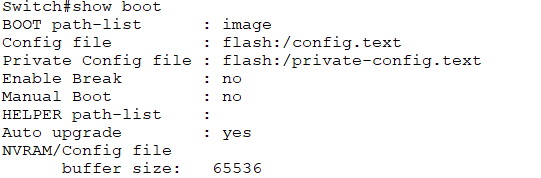
You can enter the show boot command to see what the current ios boot file is set too;
If you wanted to boot the system from a pre determined file you can use the boot system command within global configuration mode follow by flash and the file name for example; (FOC.bin is a predetermined boot file)
Cisco Switch LED Indicators
System LED (SYST): Shows whether the system is receiving power and
functioning properly.
Redundant Power Supply LED (RPS): Shows the RPS status.
Port Status LED (STAT): When green, indicates port status mode is
selected, which is the default. Port status can then be understood by the
light associated with each port.
Port Duplex LED (DUPLX): When green, indicates port duplex mode is
selected. Port duplex can then be understood by the light associated with
each port.
Port Speed LED (SPEED): When green, indicates port speed mode is
selected. Port speed can then be understood by the light associated with
each port.
Power over Ethernet LED (PoE): Present if the switch supports PoE.
Indicates the PoE status of ports on the switch.
The Mode button is used to move between the different modes – STAT,
DUPLX, SPEED, and PoE