Bandwidth - The maximum amount of data that can be transmitted and received over a specific period of time ( size of the pipe in water terms)
Latency - Latency measures delays in transmission dependent on network conditions (how quickly does the water travel down the pipe)
Throughput - The amount of data able to be transmitted over a specific period of time ( amount of water in the pipe)
Goodput - The amount of actual data received taking into account traffic overheads and network conditions (calculation Throughput- traffic overhead)
Dependent on the client and the environment selecting the most suitable network media is a crucial decision for a network engineer. It is not as simple as choosing the best all the time as it may not suit a particular client's budget or infrastructure that they already have in place. Below we will discuss the different options and technicalities.
Wired
Copper Unshielded Twisted Pair (UTP)
UTP is the most common type of copper cabling used in telephone wiring and local area networks. The twisting of the wires is done to reduce crosstalk and static interference. It is low cost, easy to install, robust and easy to replace. Shielded cabling is usually used in coaxial cabling for TV's
T568A vs T568B
T568A and T568B are the network termination standards. Below are the differences in pin layout. T568A is the preferred layout due to it preferring backwards compatibility.
Copper cabling does have its limitations. Limitations include:
Susceptible to attenuation, meaning signal strength is reduced every the further away from the source you get. Imagine a house at the end of the street and a house next to the patch box at the front of the street. The house at the end of the street will have reduced bandwidth.
Corrosion is common and therefore often needs to be replaced.
Bandwidth limitations to around 100Gbps
Distance is limited to around 100 metres
Straight through vs cross over cabling
When a device is connected to a device that is the same the preferred option is to use a cross over cable which reverses the sending and receiving transmission, whereas when a devices are different ie switch to router a straight through cable is preferred.
Auto-MDI/MDIX is a feature on switches that automatically detects what type of port is connected at the other end and swaps the transmission and receiving pins. This allows the network to still function if the desired cable is not used.
Fibre Optic
Fibre optic cabling is made up of plastic or glass and transmits signals in the form of light using dispersion which is the spreading out of light over time. It offers significantly more bandwidth (upto 60Tbps). It is thin and lightweight but is fragile. Installation costs are high and the skillset needed to splice a cable is high. Fibre cabling does not suffer from attenuation or static interference and can travel to ranges of 100km for the highest quality, making it the preferred option for under the sea cabling. Below is a short animation of how cabling is laid under the sea.
Single mode vs multi mode fibre
When choosing between multimode and single mode fibre it comes down to cost and client requirements. Typically multimode fibre is used in data centres as it is limited to approximately 550 metres, but external cabling ie around cities, under the sea etc. single mode is used because it can travel much further and allows for higher bandwidth and lower levels of attenuation. From the below diagram it is clear that multimode can suffer from lower bandwidth due to light dispersion and attenuation occurring along the cabling
Wireless
Before we go into wireless technical details it is important to know that at wireless access point is simply an extension of a copper network and is not a wireless network itself.
Wireless networks are configured from a router or a number of routers. Frequency is often a common discussion point. Most routers these days operate with dual band frequencies but it is important to understand the complexities of both.
2.4Ghz - can travel further and through thick walls but is limited on data rates
5Ghz - limited distance travelled, struggles penetrating objects but has higher data rates than 2.4Ghz
Manchester Encoding
Within data transmission Manchester encoding is a form of digital encoding where bits are represented by transitions from one state too another. An example is shown below where 1's are peaked and 0s are the dips. This takes place at the physical layer of the OSI model
Other key terms
Half Duplex and Full Duplex - Half Duplex works like a walkie - talkie waits to receive before it can send whereas full duplex can send and receive at the same time
DHCPv6 as a concept is very similar to version 4. There are some key differences that we need to know. DHCPv6 supports two very different methods; Stateful and stateless configurations.
Stateful
Stateful configuration works pretty much the same as DHCPv4. The DHCP server assigns the IP address to the client. When DHCPv6 addresses are being sent from a server to a client it uses UDP destination port 546
Stateless (SLAAC)
Stateless on the other hand uses autoconfiguration.Routers running IPv6 can give the prefix of the network and a gateway address to clients looking for an IPv6 address. IPv6 uses the Neighbour Discovery, and one of the things this protocol offers is Route Solicitation and Router Advertisement messages that help an IPv6 device configure an IPv6 address automatically. The router is configured to send out Router advertisements periodically.
Router Advertisement messages inform hosts what to do - There are three flags in the RA messages that play important role in defining how dynamic addressing works on this segment:
A-flag - if it is set to 1, this informs hosts that they can auto-generate GUA address using SLAAC. If it is set to 0 means that auto-configuration is not allowed for this segment.
O-flag - if it is set to 1, this informs hosts that they can obtain a DNS server list and a domain name from a Stateless DHCPv6 server, but not addressing information. Typically it works in conjunction with SLAAC for auto-addressing and both the A-flag and the O-flag are set to 1.
M-flag - if it is set to 1, this informs hosts that they can obtain a global address as well as DNS and a domain name from a Stateful DHCPv6 server. Typically this means that auto-addressing using SLAAC is not allowed on this segment and both the A-flag and the O-flag are set to 0.
A host sends out a router solicitation message which is a multicast address for all routers which is FF02::2. The Router Advertisement contains the Prefix Information (prefix (network address), prefix length (subnet mask), and default gateway). The host uses this information to generate an IPv6 address (global unicast address or GUA) for itself. The host then employs Duplicate Address Detection to ensure that its address is unique. 2. On the router use the below configurations from the screenshot;
Configurations
Lets look at how we configure SLAAC;
1. Build a simple network similar to the below
-ipv6 unicast-routing (enables the router for IPv6 routing)
-interface gigabitethernet0/0/0 (this is the particular interface being used for the connection to the switch)
-ipv6 address (is an IPv6 address which in this instance in the address of the router)
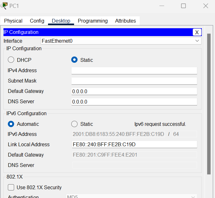
3.On each PC change the IPv6 configuration to automatic.
You will now find that the PC generates a Global Unicast Ipv6 Address on its own, with the Default Gateway address and the Link-Local Address from the Router Advertisement.
Ipv6, SLAAC and EUI
The EUI (extended Unique Identifier) uses the MAC address to generate a unique 64 bit interface ID. An Ipv6 address is 128bits and a MAC address is 48 bits so an operation needs to be performed.
The hexadecimal value of FFF0(16-bits) is added in the middle of the 48-bit mac address.
The 7th bit from the start is toggled from 0 to 1.
For example:
For the MAC address FC:99:47:75:CE:E0 the steps are performed as shown in the below:
Cisco routers are configured to use the EUI-64 ID generation by default.
Here is a video showing the configuration in action;
DHCP dynamically allocates an IP address from either a pre configured router or a server. DHCP is managed centrally and saves administration time but if configured incorrectly can lead to devices not being able to connect to the network. When a device is given an IP address the DHCP server also gives out a subnet mask, DNS information and default gateway. DHCP communicates on UDP source port 68 and destination port 67. Below is an image of the process when DHCP is enabled on a client. Discover -> Offer -> Request -> Acknowledge
-During a DHCP discover message a client uses layer 2 and layer 3 broadcast message to find a DHCP server.
-During the offer message a server sends a unicast message to the requesting client.
-During the request message the client returns with a broadcast message to the server requesting an IP address
-Finally the acknowledgement message is a unicast message from the server to client with the IP address.
The key terms within DHCP configurations are;
DHCP pool
Network address
Default Gateway
Subnet Mask
Here is a simple video of IPv4 DHCP configurations in packet tracer showing the benefits through automation;